LED design
Design a moving field of light either as an image or as a list of color values. Shaders suit textures, turbulence and other image-based effects; arrays give you direct control over the rhythm and ordering of individual channels. Both approaches can be previewed before connecting LEDs.
score provides authoring tools for RGB data and connections to LED hardware through DMX or directly through SPI. Choose a technique below, then adapt its output to your controller’s channel layout.
Tools of the trade
List of useful devices
- Art-Net Device: when created without any fixture, the raw DMX channels will be available, as well as the ability to send raw messages to the whole device.
List of useful objects
Most of the objects useful for LED shows are in the process library, in the Control > Mappings and Control > Generators categories.
To generate LED content from shaders, one can use the Lightness Computer object which will convert an input texture into a series of pixels.
To visualize LED output, one can use the LED View process.
Controlling LEDs from a shader
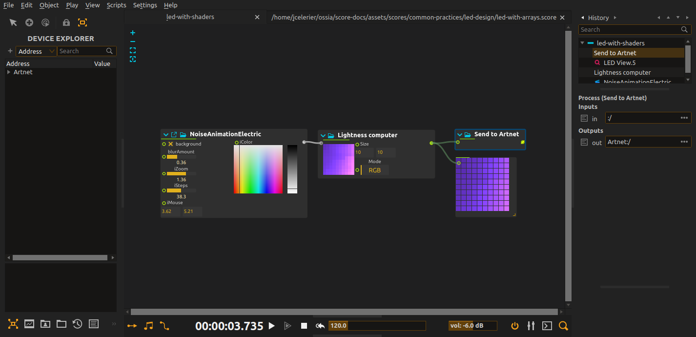
Download the example score here.
Turn an animated texture into a low-resolution field of light. In the downloadable patch, an electric-noise shader supplies the image and Lightness Computer samples it on a 10×10 grid. Its RGB values feed both an LED preview and a device output, so the same pattern can be studied on screen before it reaches a physical installation.
Start playback and watch the preview while changing the shader’s zoom or color. Lower Lightness Computer’s Size: fine detail in the image disappears at the coarser sampling resolution. The enabled 8-bit conversion produces channel values for the preview’s RGB mode.
The saved device uses sACN and points to the local machine, not your LED controller. Before connecting hardware, configure its destination and universe, check the RGB channel order and keep the sample count within the available channels. The shader needs a graphics backend; no external image is required. Its embedded source credits nimitz under CC BY-NC-SA 3.0, which matters when reusing it.
Creating LEDs from generative array computations
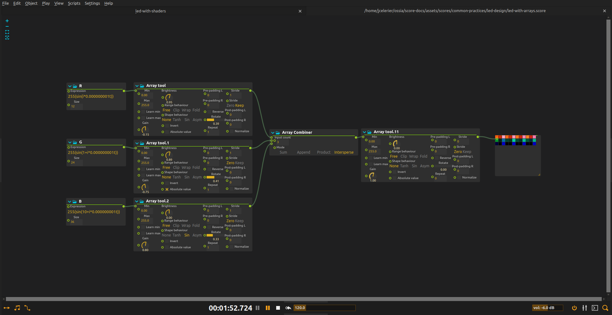
Use expressions when the pattern should grow from timing, repetition or another numerical data source instead of a texture. In the array example, differently phased sine waves become sections of a changing color strip. It generates the values without shader rendering.
For a design in which you want independent red, green and blue channels, the general workflow is:
- Generate equally sized arrays for R, G and B, optionally adding W for RGBW. Arraygen can calculate one value per element.
- Use Array combiner in Intersperse mode to turn separate color arrays into consecutive pixels:
[R, R, R],[G, G, G]and[B, B, B]become[R, G, B, R, G, B, R, G, B]. - Use Array tool to adjust gain, constrain the output range or add spacing before sending the result onward.
The downloadable array patch uses a different arrangement: Append joins whole arrays end to end, so each generator controls a section of the strip instead of a color channel.
For a complete patch, see Generate LED arrays with expressions.
Combining multiple LED strips in one array
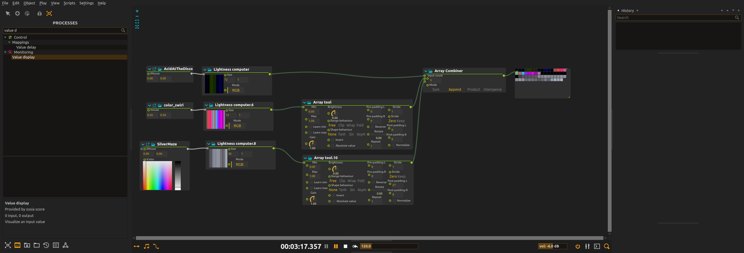
Download the combination example.
Give different sections of an installation their own animation while sending one continuous list of colors. The combination example samples three shaders, then joins their arrays with Array combiner in Append mode. It places the sections one after another instead of blending their images.
Use Array tool on an individual section to change its brightness or add dark spacing without altering the others. Padding is counted in channel values, not pixels: use multiples of three for complete RGB pixels and check the final length against your hardware layout.
See Combine shader LED arrays for a downloadable patch and its routing.